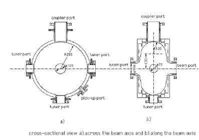
Figure 1. Cross-sectional view of the cavity.
Four points were optimized for the cavity design;
Detail on suppression of HOMs can be seen in references.
H. Ego, et al., N.I.M.400 (1997) 195-212p
H. Ego, et al., N.I.M.383 (1996) 325-336p
To suppress the coupled-bunch instabilities arising from the coupling impedance with higher order mode resonances;
Figure 1. Cross-sectional view of the cavity.
There are seven ports in the cavity;
calculated RF characteristics of TM010-like mode and of the HOMs
| modes | frequency (MHz) | unloaded Q | half power
band width (kHz) |
shunt impedance
(MW or MW/m) |
threshold
current (mA) |
| TM010 | 508 | 44100 | 11.5 | 6.7 | |
| TE111 | 712 | 56000 | 12.7 | 4.1 | 555 |
| TM110 | 763 | 52800 | 14.5 | 10.7 | 188 |
| TM011 | 905 | 43500 | 20.8 | 2.8 | 208 |
| TM111 | 1077 | 44000 | 24.5 | 13.7 | 166 |
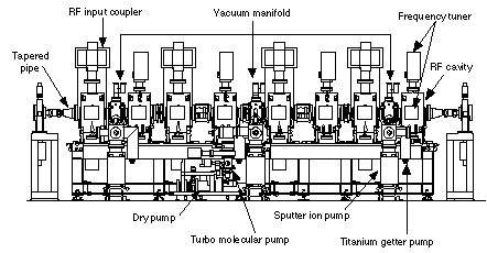
Figure 2. Layout of the cavities at an RF station.
coupling of the input coupler
The coupling constant of the input coupler is adjusted to 2.